

Digital Instrumentation refers to devices built using digital technology and electronic components, which are used to measure, monitor, and control physical quantities like temperature, pressure, current, voltage, etc. These digital instruments process the signals using digital logic (0 or 1) and usually display the information numerically.
Common Digital Instruments in Industrial Automation
- Push Button Switch: A common switch used to start or stop a machine.
- Emergency Stop Switch: Used to immediately shut down the entire system in an emergency situation.
- Selector Switch: Used to select different modes (e.g., Manual/Auto).
- Limit Switch: Gives a signal when a machine reaches its predetermined operational limit.
- Photo and Proximity Sensor: A sensor used to detect objects based on light or proximity.
- Temperature Switch: Gives an on/off signal when a specific temperature is reached.
- Pressure Switch: Operates when a specified pressure level is exceeded.
- Flow Switch:Detects the flow of liquid or gas and sends a control signal.
- Level Sensor or Switch: Used to send a signal by determining the height of the liquid in a tank.
- Indicator Lamp: A light used to indicate the status or position of the machine.
- Relay: An electromagnetic switch used to control a circuit from one point.
- Overload Relay: A device that trips to protect the system when a motor’s circuit current exceeds a safe limit.
- Magnetic Contactor: An electromagnetic device used to turn heavy loads on or off.
- Buzzer: A sound device used to give warnings or alarms.
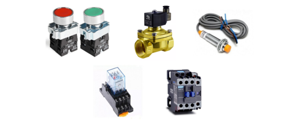
Digital Input
Digital Input refers to:
It is a signal or information that enters an automation system (such as a PLC or Microcontroller) and whose value can only be in one of two states: ON (1) or OFF (0).
Examples:
- Pressing a push button results in an input of (1).
- When a limit switch is activated, the input is (1); when it is deactivated (closed/not pressed), the input is (0).
- When a proximity sensor detects an object, the input is (1).
Digital Output
Digital Output refers to:
It is a signal or instruction that is sent from the controller (PLC/Microcontroller) to an external device, and whose value is either ON (1) or OFF (0).
Examples:
- The controller gives an output of (1) to turn on a lamp.
- The controller sends a signal of (1) to activate a relay.
- The controller gives an output to sound a buzzer.
Relay Logic Control
Relay Logic Control is an old but effective method where relays (electromagnetic switches) are used to control the ON/OFF state of mechanical processes according to specific logic.
How Does Relay Logic Control Work
- It involves various input devices (e.g., Push Buttons, Limit Switches) and output devices (e.g., Motors, Lamps) connected via relays.
- Every relay consists of a Coil and one or more Contacts (NO/NC).
- When a signal comes from an input, the relay is activated, and the contacts change state (Normally Open➡️ Closed, or vice-versa), thereby activating the output.
Example (Simplified):
Suppose you are controlling a motor with a start/stop button:
- Pressing the Start Button ➡️ Relay Activates ➡️ Contact Closes ➡️Motor Starts.
- Pressing the Stop Button ➡️ Relay Deactivates ➡️ Contact ➡️Opens Again ➡️ Motor Stops.
This way, a logic is created using relays and buttons, which is called a Relay Logic Control Circuit!
Elements of an Ideal Circuit
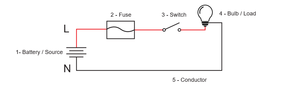
1. Voltage Source
- It acts as a source of electrical energy or power in the circuit.
- Examples: Batteries, power supplies, generators.
2. Protective Device
- Protects the circuit or equipment from overcurrent, short circuits, overloads, etc.
- Examples: Fuses, circuit breakers, overload relays.
3. Controlling Device
- It controls the ON/OFF time and method of operation of the circuit.
- Examples: Switches, relays, contactors, PLC.
4. Load
- This is the component that receives and uses the electrical energy.
- Examples: Motors, bulbs, fans, heaters.
5. Conductor
- It helps carry electricity from the voltage source to the load.
- Examples: Copper wire, aluminum wire.