
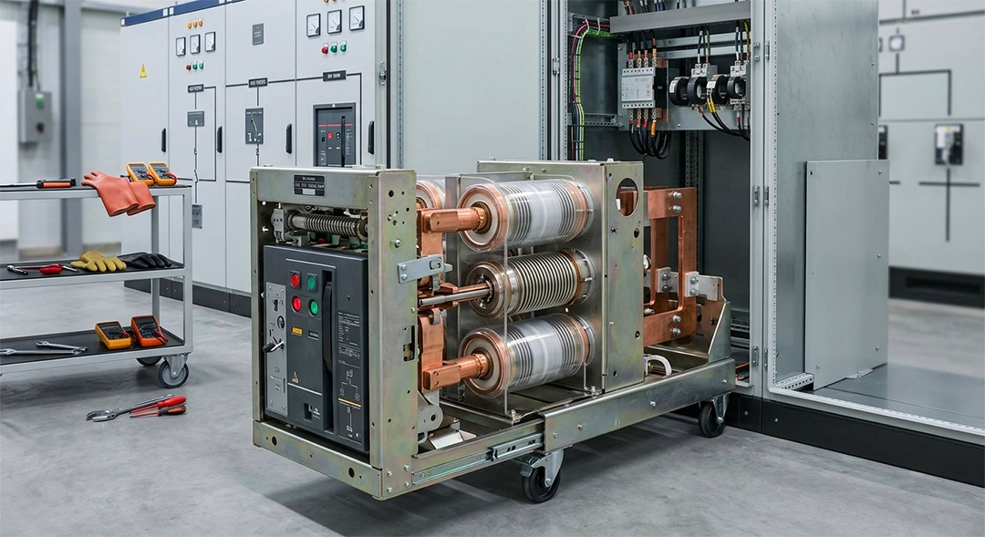
In medium-voltage (MV) electrical distribution networks, system safety and reliability depend heavily on circuit breakers. Among the various technologies developed over the decades, the Vacuum Circuit Breaker (VCB) has emerged as the global industry standard for medium-voltage switchgear.
This comprehensive guide breaks down the core technology, structural elements, fundamental operating physics, technical standard ratings, and step-by-step engineering selection criteria for VCBs.
1. What is a Vacuum Circuit Breaker (VCB)?
A Vacuum Circuit Breaker is an electrical switching device designed to open or close an electrical circuit under normal or abnormal (short-circuit fault) conditions. The defining characteristic of a VCB is that the initiation of the electrical arc and its subsequent extinction take place within an ultra-high vacuum environment inside a sealed component known as a vacuum interrupter.
Historically, electrical networks relied on bulk oil, minimum oil, or air-blast circuit breakers. However, these older mediums presented serious fire hazards, large space footprints, and substantial maintenance demands. While Sulfur Hexafluoride SF6 gas remains highly effective for high-voltage (HV) transmission lines, it is a potent greenhouse gas. For medium-voltage systems (3.3 KV to 36 kV ), the VCB provides an ideal balance of compact size, environmental safety, and exceptional structural durability.
2. Internal Design & Construction
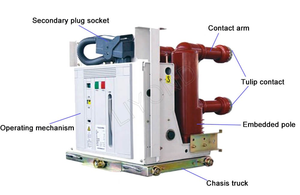
The structure of a VCB is divided into two distinct assemblies: the high-voltage primary switching elements (the vacuum interrupter poles) and the low-voltage mechanical operating actuator.
The Vacuum Interrupter (VI) Core
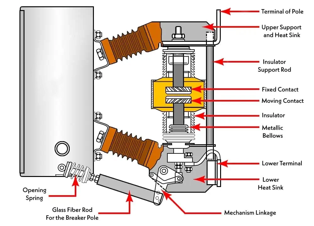
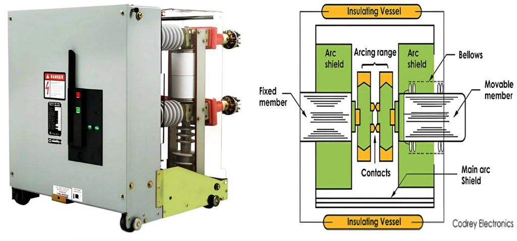
The heart of the VCB is the vacuum interrupter bottle. It consists of an airtight, hermetically sealed envelope made of high-grade alumina ceramic or glass insulating cylinders capped by stainless-steel endplates. Inside this unit reside:
- Fixed Contact: Welded permanently via a structural copper stem to one end of the interrupter shell.
- Moving Contact: Connected to a translating copper stem that travels linearly through a metallic bellows assembly.
- Stainless-Steel Bellows: A flexible, accordion-like metal component that allows absolute mechanical motion of the moving contact while maintaining a reliable, long-term vacuum seal against atmospheric pressure.
- Arc Shield (Vapor Shield): A metallic cylinder surrounding the contacts. During an arc event, it catches metal vapor erupted from the contacts, preventing it from condensing on the outer ceramic walls and compromising the structural insulation.
Contact Materials and Geometries
Standard pure metals are susceptible to localized welding under high contact forces and short-circuit faults. Consequently, VCB contacts are manufactured from specialized composite powder metallurgy alloys:
- Copper-Chromium (CuCr): The global standard material for medium-voltage power applications. It offers an excellent combination of high electrical conductivity, low current chopping, high resistance to arc erosion, and low contact welding.
- Silver-Tungsten (AgW): Typically deployed in low-voltage or highly specialized control systems where minimized contact resistance over a long life is paramount.
Additionally, the contacts are engineered with slotted or spiral shapes to generate either a Radial Magnetic Field (RMF) or an Axial Magnetic Field (AMF). These fields force the electrical arc to rapidly rotate or stay in a diffuse state across the surface rather than anchoring to a single spot, mitigating severe localized thermal melting.
3. Fundamental Working Principle
The operating sequence of a VCB is governed by the rapid physical separation of its contacts and the subsequent behavior of the resulting plasma channel under a vacuum.
Arc Production and Dynamics
When the protective relay detects a short-circuit fault, it triggers the breaker’s external spring-charged or magnetic actuator. As the moving contact accelerates away from the fixed contact, the physical contact area shrinks dramatically. This causes the localized current density to spike towards infinity. The resulting extreme Joule heating raises temperatures past the melting point of the contact material, causing a micro-pool of metal to boil and vaporize.
This metal vapor fills the opening gap and becomes ionized, forming a highly conductive plasma arc. It is critical to recognize that the arc is not sustained by an ionized ambient gas (as in air or $SF_6$ breakers), but is composed exclusively of vaporized contact metal.
Arc Interruption and Dielectric Recovery
As the alternating current wave moves naturally toward its next zero-crossing point, the thermal energy entering the arc channel plummets. At the exact current zero-cross point, the emission of metal vapor ceases entirely.
Because of the severe pressure differential between the high-density vapor arc and the surrounding ultra-high vacuum environment
the metal vapor expands outward at supersonic speeds (often exceeding 103 m/s and condenses onto the metal vapor shields. Within microseconds after the current zero, the gap is completely cleared of charge carriers. The dielectric strength of the vacuum gap recovers at a rate of tens of kilovolts per microsecond (KV/µs).
If the rate of recovery of the gap’s dielectric strength exceeds the Transient Recovery Voltage (TRV) imposed by the external inductive/capacitive electrical grid, the arc is permanently extinguished, and the circuit is successfully isolated.
The Phenomenon of Current Chopping: > Because vacuum interrupters are exceptionally efficient arc quenchers, they can occasionally extinguish the arc prematurely before the natural sinusoidal current zero-crossing is reached. This abrupt interruption of a non-zero current causes a high rate of change of current di/dt. When passed through inductive system components (like transformers or unloaded motors), it generates a severe voltage surge defined by:
Modern CuCr contact formulations are engineered to limit this chopping current to extremely low values (typically below 2A to 3A), minimizing transient overvoltages.
4. Classification and Types of VCBs
Vacuum Circuit Breakers are categorized primarily by their structural deployment environment and their physical mounting mechanisms.
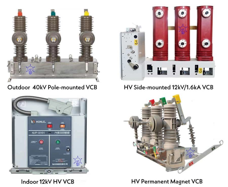
By Installation Environment
- Indoor VCBs: Designed to operate safely inside metal-clad switchgear enclosures, sheltered from ambient dust, moisture, rain, and external pollutants. They feature highly compact space envelopes and are standard inside industrial plants, commercial buildings, and indoor step-down substations.
- Outdoor VCBs: Engineered with a completely weatherproof enclosure, utilizing high-creepage porcelain or polymer structural insulators to isolate the line terminals from the grounded structure. These are deployed directly in open-yard distribution substations, overhead pole mounts, and rural grids.
By Mechanical Mounting Arrangement
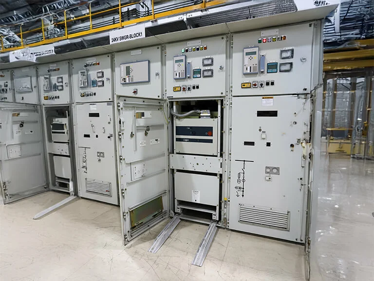
- Fixed-Type VCBs: The breaker chassis is bolted directly onto the switchgear structural framework. Primary electrical connections are terminated via busbar bolting. Isolating the breaker for maintenance requires completely de-energizing the main section busbars.
- Withdrawable / Draw-out Type VCBs: The breaker assembly is mounted onto a movable wheeled truck or racking mechanism. It features self-aligning primary isolating cluster finger contacts. The breaker can be easily “racked out” from the connected service position to a disconnected test position, isolating it safely behind protective automatic shutters without de-energizing the upstream switchgear lineup.
5. Key Technical Ratings (IEC 62271-100 Standard)
To ensure safe specification and adherence to international guidelines such as the IEC 62271-100 and ANSI/IEEE C37.06, engineers must evaluate a core set of standard ratings:
| Technical Parameter | Standard Range (Typical MV Grid) | Engineering Definition & Description |
| Rated Voltage (Ur) | 7.2 KV, 12 KV, 17.5 KV, 24 KV, 36 KV | The maximum continuous RMS power-frequency voltage that the breaker housing can safely isolate under standard operating conditions. |
| Rated Normal Current (In) | 630A, 1250A, 2000A, 3150A, 4000A | The continuous RMS current the breaker can carry indefinitely without exceeding designated thermal limits on the copper contacts and bus joints. |
| Power Frequency Withstand Voltage | 28 KV to 70 KV (RMS) | The 1-minute AC test voltage used to verify structural dielectric insulation integrity against short-duration grid power fluctuations. |
| Lightning Impulse Withstand (BIL) | 75 KV, 95 KV, 125 KV, 170 KV, (Peak) | The peak crest voltage of a standard 1.2/50 µs wave pulse that the system can withstand, simulating direct atmospheric lightning surges. |
| Short-Circuit Breaking Current (Isc) | 25 KV, 31.5 KA, 40 KA, 50 KA | The ultimate RMS value of symmetrical short-circuit fault current that the vacuum interrupter can break safely at natural current zero. |
| Short-Circuit Making Current (Ima) | 63 kA, 125 kA (Peak) | The peak dynamic current the breaker mechanisms can close against during an active, un-cleared fault. Statistically scaled as: Ima ≈ 2.5 x Isc |
| Rated Short-Time Withstand Current | 1 Sec or 3 Sec (matching Isc) | The capability of the internal closed contacts to carry a full fault current for a brief duration without experiencing thermal melting or mechanical deformation. |
6. Comprehensive VCB Selection Criteria
Selecting the correct VCB for an industrial facility or utility substation requires a systematic workflow based on electrical system parameters, environmental context, and load traits.
Step 1: System Voltage and Insulation Coordination
The nominal network operating voltage must always sit below the breaker’s rated maximum voltage (Ur). For instance, a standard 11KV primary distribution grid requires a rated breaker capacity of at least 12KV to accommodate continuous high-voltage tolerances. Additionally, ensure the Basic Insulation Level (BIL) matches the local surge-arrester protection scheme.
Step 2: Continuous Thermal Load Calculations
Calculate the maximum anticipated continuous current under peak operational loads, accounting for potential future expansions. The standard rating is typically chosen with a safety factor of 20% over maximum load calculations:
Step 3: Symmetrical and Asymmetrical Short-Circuit Capacity
A complete 3-phase fault simulation study must determine the prospective short-circuit kA at the node of installation. The breaker’s Isc capacity must exceed this value. For grids experiencing high inductive loads or located close to heavy generation sources, a significant DC offset component may exist during the first cycle of a fault. The breaker must be checked for its rated percentage of DC component at the point of contact separation.
Step 4: Mechanical and Environmental De-rating Factors
Standard ratings are calibrated for altitudes below 1000 meters and ambient temperatures up to 40°C.
- Altitude De-rating: At altitudes exceeding 1000m, the lower air density reduces external dielectric breakdown voltage and cooling efficiency. The external insulation must be scaled up or the operating limits de-rated.
- Temperature De-rating: If operating inside enclosed, unventilated switchgear rooms where ambient temperatures regularly exceed 40°C, the continuous normal current limit must be de-rated to prevent thermal runaway at the contacts.
7. Advantages and Limitations of VCB Technology
Key Engineering Advantages
- Exceptional Operational Life: Mechanical and electrical life cycles extend past 10,000 to 30,000 operations, significantly outclassing alternative designs.
- Minimal Maintenance: The primary vacuum bottle structure is hermetically sealed for life, eliminating the recurring need for contact resurfacing or dielectric liquid filtration.
- Compact Footprint: The very high dielectric breakdown strength of the vacuum enables ultra-short gap distances, meaning vacuum interrupters require minimal space.
- Eco-Friendly and Safe: No hazardous oil leakage issues, zero toxic gas emissions (unlike SF6 greenhouse gases), and absolutely zero structural fire or blast hazards.
Key Technical Limitations
- Current Chopping Surges: High arc-quenching capability can cause high inductive voltage transients, necessitating surge arresters or RC snubbers.
- High-Voltage Limitations: Economically and structurally optimized for medium-voltage (≤ 36 KV to 72.5 KV). Higher voltages require complex, multi-bottle series designs.
- Loss of Vacuum Risk: If a micro-puncture occurs in the metallic bellows, the vacuum is compromised. It cannot break faults under normal air atmospheric pressures.
- Specialized Diagnostic Needs: Finding a vacuum leak requires high-pot or magnetron vacuum testing equipment.
8. Routine Maintenance and Diagnostic Testing
While the vacuum bottle itself is maintenance-free, ensuring the long-term operational integrity of the overall assembly requires systematic periodic checks:
- Insulation Integrity / High-Potential (Hi-Pot) Test: An industrial AC or DC dielectric test is applied across the open contacts of the VCB. If the vacuum interrupter has suffered an atmospheric leak, structural flashover will occur at low voltages, signaling a replacement requirement.
- Contact Resistance Measurement (Ductor Test): A heavy DC current (typically ≥ 100A) is driven through the closed pole assembly. The resulting voltage drop yields the contact resistance in micro-ohms (µΩ). Spikes in resistance point to contact wear or degraded joint mechanical pressure.
- Contact Erosion Check: Manufacturers place physical reference wear indicators or scribed grooves on the external moving copper stem. When these marks disappear, it demonstrates that arc ablation has worn down the internal contacts past safe working limits.
- Mechanism Synchronization and Timing Test: Digital timing analyzers track the precise millisecond opening and closing sequence across all three phases. Phase non-simultaneity must remain strictly below 2ms to prevent dangerous neutral voltage unbalances during normal switching operations.